- Published on
Self-Balancing Robot Part 2: Motor Control

Motor Control
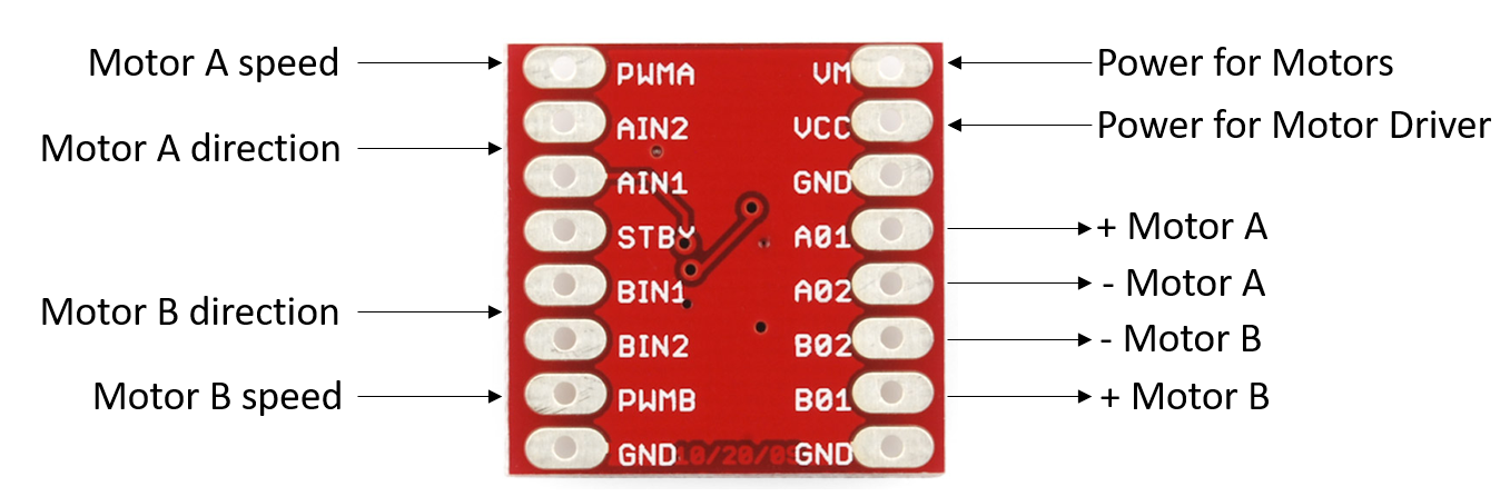
There are 3 components necessary for motor control. The arduino, a motor driver, and the dc motors. Unlike the arduino, the dc motors require a lot of current to function. The motor driver interfaces between the arduino and dc motors and essentially amplifies the low current from the arduino, into a higher one for the motors. The following diagram shows the function of each pin for a TB6612FNG motor driver. More detail can be found here.
The manufacturer provides a truth table for the motor driver.
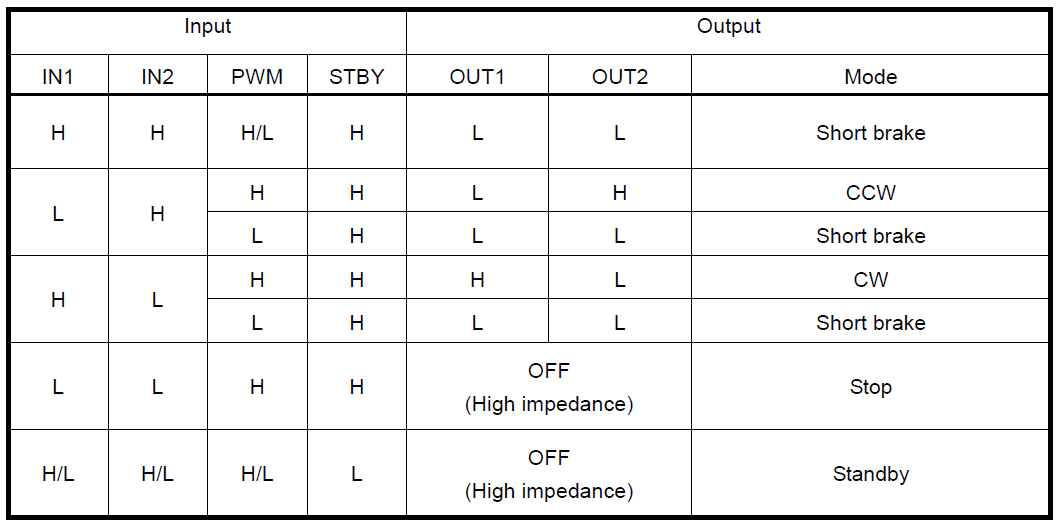
In order to rotate a motor CCW, we'll need to send a high level signal to the IN2 pin, and a low level signal to the IN1 pin. A Two-Way Schmitt Trigger Reverser is used to reverse the signals of IN1 and IN2, so if we send a high level signal to IN1, a low level signal will be automatically sent to IN2. Here's the connections we'll use:
Let's define a class for the motor in a file called "Motor.h".
class Motor {
private:
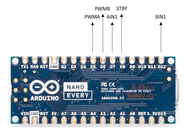
#define AIN1 7 // AIN1 pin on motor driver connects to D7 on arduino
#define PWMA 5 // PWMA pin -> D5
#define BIN1 12 // BIN1 -> D12
#define PWMB 6 // PWMB -> D6
#define STBY 8 // STBY -> D8
public:
void pinInit(); // assign pins
void Forward(int speed); // move forward
void Reverse(int speed); // move in reverse
};
Our pinInit() function will assign the digital pins of the arduino as output pins, and we'll set the STBY pin to always be HIGH. The Forward function will send signals to rotate the wheels CCW and the Reverse function will do the opposite. We'll add the functions in "Motor.cpp".
#include <Arduino.h>
#include "Motor.h"

void Motor::pinInit(){
    // sets pin as output
    pinMode(AIN1, OUTPUT);
    pinMode(BIN1, OUTPUT);
    pinMode(PWMA_LEFT, OUTPUT);
    pinMode(PWMB_RIGHT, OUTPUT);
    pinMode(STBY_PIN, OUTPUT);
    // sets the STBY pin on
    digitalWrite(STBY_PIN, HIGH);
}

void Motor::Forward(int speed){
    digitalWrite(AIN1, 0); // for CCW rotation
    digitalWrite(BIN1, 0);
    analogWrite(PWMA, speed); // set speed of motors, betwen 0 and 255
    analogWrite(PWMB, speed);
}

void Motor::Reverse(int speed){
    digitalWrite(AIN1, 1); // for CW rotation
    digitalWrite(BIN1, 1);
    analogWrite(PWMA, speed);
    analogWrite(PWMB, speed);
}
Let's see an example of how the above can be used. Open an arduino .ino file and upload the following:
#include "Motor.h"
#define SPEED 255 // anywhere between 0-255

Motor Motor; // instantiate class

void setup() {
    Motor.pinInit();
}

void loop() {
    Motor.Forward(SPEED); // run motors CCW
    delay(5000); // wait for 5s
    Motor.Reverse(SPEED); // run motors CW
    delay(5000);
}
That's all we need for the motors to run!
PID Algorithm
We've implemented a method to detect the angle of inclination of the robot, and a method to drive the motors. Now, we'll learn how we can use a PID algorithm to bring the two together to control our robot. The PID algorithm determines a response to a variable by continually calculating the difference between the desired value of the variable and the measured value. For the self-balancing robot, we are measuring the angle of inclination using the MPU6050 sensor. The desired value of this variable is the angle needed for the robot to be in an upright position. As discussed before, when the robot is inclined, we will need to send a signal to the motors to rotate in the direction of inclination. The PID algorithm will adjust the speed of the motors needed to balance the system.
The formula for this algorithm is:
is the proportional term, is the integral term, and is the derivative term. The error term, is the difference between the desired value and the measured value. , , and are the coefficients we will "tune" in order to achieve an optimal response.
Proportional Term
is how proportional we want our response to be. If we have a large error, will calculate a proportionally large response. This term enables a fast response but tends to overshoot.
Integral Term
The integral term determines a response based on the accumulation of error. The previously calculated error term is added to the current error term and multiplied by the time in-between each calculation. The response produced by this term factors in the error that should have been eliminated previously.
Derivative Term
The derivative term bases its response on the rate of change of the error, which helps reduce overshoot. This term acts opposite to the integral term in that it tries to predict system behaviour.
Implementing PID Algorithm
We'll program a basic PID algorithm to achieve some control of our robot. The desired value we need to keep the robot upright is our angle in the upright position. In my case, when the robot is upright my ay angle is roughly 0. Therefore, I'll use the ay angle for my PID algorithm. When this angle is not 0, I need to tell my motors to move. When the robot tips forward I get a positive angle, and when it tips backward I get a negative angle. I can use this information to determine whether to rotate the wheels forwards or backwards. Let's make a function to compute our PID output and define some variables.
// PID Variables
float previousTime = 0;
float prevErr = 0;
float currentTime, deltaTime, error, sumErr, dErr, pid;
float desired = 0; // desired angle is 0 degrees
float Kp = 30;
float Ki = 10;
float Kd = 1;

float PID(float measured){
    // PID calculations
}
The PID function will take the measured angle as an input. For the integral and derivative terms, we need the time difference between measurements for the calculation.
// PID Variables
float previousTime = 0;
float prevErr = 0;
float currentTime, deltaTime, error, sumErr, dErr, pid;
float desired = 0; // desired angle is 0 degrees
float Kp = 30; // need to tune these values
float Ki = 10;
float Kd = 1;

float PID(float measured){
    // PID calculations

    // time calcs
    currentTime = millis();
    deltaTime = currentTime-previousTime;

}
The error, sum of the errors, and derivative of the error needs to calculated.
// PID Variables
float previousTime = 0;
float prevErr = 0;
float currentTime, deltaTime, error, sumErr, dErr, pid;
float desired = 0; // desired angle is 0 degrees
float Kp = 30;
float Ki = 10;
float Kd = 1;

float PID(float measured){
    // PID calculations

    // time calcs
    currentTime = millis();
    deltaTime = currentTime-previousTime;

    // error calcs
    error = abs(desired - measured);
    sumErr += error*deltaTime;
    dErr = (error-prevErr)/deltaTime;

}
Next, we will calculate the PID output. The motors PWM output limit is 255, therefore if the PID calculation is greater than 255 we need to set it to 255. If the value is less than 0, we will set it to 0. Also, if the robot tips over completely we want to turn off the motors so they don't keep spinning.
// PID Variables
float previousTime = 0;
float prevErr = 0;
float currentTime, deltaTime, error, sumErr, dErr, pid;
float desired = 0; // desired angle is 0 degrees
float Kp = 30;
float Ki = 10;
float Kd = 1;

float PID(float measured){
    // PID calculations

    // time calcs
    currentTime = millis();
    deltaTime = currentTime-previousTime;

    // error calcs
    error = abs(desired - measured);
    sumErr += error*deltaTime;
    dErr = (error-prevErr)/deltaTime;

    // pid calc
    pid = Kp*error+Ki*sumErr-Kd*dErr;

    // keep values for next iteration
    prevErr = error;
    previousTime = currentTime;

    if (pid > 255){
        pid = 255;
    }

    if (pid < 0){
        pid = 0;
    }

    // stop motors if robot tips over
    if (abs(measured) > 30){
        pid = 0;
    }

    return pid;

}
The PID function can now be used in the loop to continually updated the motor speed. Open an arduino file and add the following. When the angle is negative, the motors need to spin clockwise so I call the Motor.Reverse function. When the angle is positive, the motors need to spin counter-clockwise so I call the Motor.Forward function.
#include "Motor.h"
#include "mpu.h"

mpu mpu; // instantiate MPU class
Motor Motor; // instantiate Motor class

void setup() {
  // put your setup code here, to run once:
  mpu.init(); // initialize mpu
  Motor.pinInit(); // initialize motor pins
}

int output;

void loop() {
  // put your main code here, to run repeatedly:
  mpu.retrieveData(); // retrieves raw accelerometer data
  mpu.processData(); // converts raw data into angles
  output = PID(mpu.angleY); // compute pid using current angleY measurement


  if (mpu.angleY < 0) {
    Motor.Reverse(output);
  }

  if (mpu.angleY > 0){
    Motor.Forward(output);
  }

}

// PID Variables
float previousTime = 0;
float prevErr = 0;
float currentTime, deltaTime, error, sumErr, dErr, pid;
float desired = 0; // desired angle is 0 degrees
float Kp = 30;
float Ki = 10;
float Kd = 1;

float PID(float measured){
    // PID calculations

    // time calcs
    currentTime = millis();
    deltaTime = currentTime-previousTime;

    // error calcs
    error = abs(desired - measured);
    sumErr += error*deltaTime;
    dErr = (error-prevErr)/deltaTime;

    // pid calc
    pid = Kp*error+Ki*sumErr-Kd*dErr;

    // keep values for next iteration
    prevErr = error;
    previousTime = currentTime;

    if (pid > 255){
        pid = 255;
    }

    if (pid < 0){
        pid = 0;
    }

    // stop motors if robot tips over
    if (abs(measured) > 30){
        pid = 0;
    }

    return pid;

}
The balancing of the robot is quite jittery and eventually drifts and falls over. There are a number of ways to improve this such as using the gyroscope for angle measurements, and better tuning of the PID coefficients. We can also use the DC motor encoders to find the RPM of the motors which we can then use in a another PID calculation. Also, the PID code above is rather basic and there are several improvements that can be made. We'll work on adding these features and improving the robot in the future.