- Published on
Self-Balancing Robot Part 1: IMU

The Inverted Pendulum Problem
The self-balancing robot presented in this blog is essentially an inverted pendulum. In a regular pendulum, gravity acts on the swinging mass and brings it back towards the center.
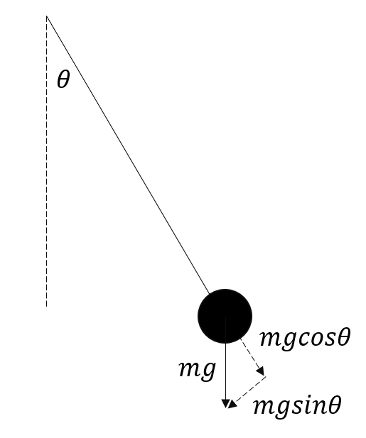
The term brings the mass back to equilibrium. In an inverted pendulum problem, we have the above pendulum flipped and hinged to a wheeled cart.
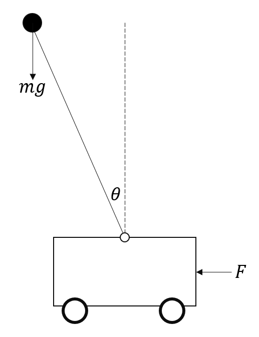
When the mass is upright (perpendicular to cart) and the system is at equilibrium. When , gravity accelerates the mass downwards and the system is unbalanced. In order to balance the system i.e. return the mass to equilibrium, we need to move the cart in the direction that the mass is tipping in. In the above figure, since the mass is falling to the left, the cart needs to move to the left to balance it. You can think of this intuitively by imagining that you're balancing a meter stick in the palm of your hand. If the meter stick falls forward, you move your hand forward until it is balanced and vice versa.
So how do we implement the above balancing technique in the robot? Firstly, we will need a sensor to detect when the system is unbalanced i.e. at an angle. When we receive a signal that the robot is tipping, we will have to signal to the motors to start spinning the wheels in that direction. The wheels will continually spin until our sensor has detected that the angle of the robot is near zero i.e. back to equilibrium.
Inertial Measurement Unit (IMU)
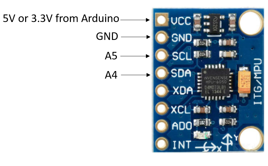
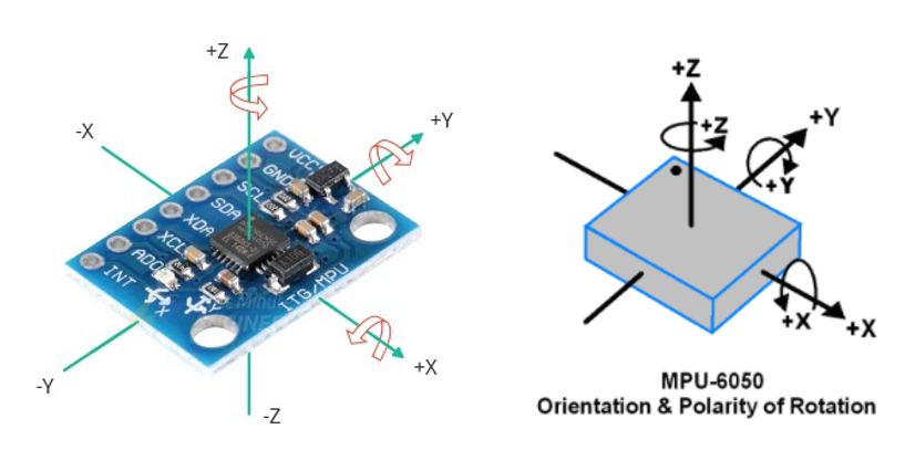
The Inertial Measurement Unit (IMU) is a sensor that can be used to detect the angle, or orientation of a body. It consists of accelerometers used to calculate linear accelerations and gyroscopes used for angular velocities. An MPU6050 is an IMU we can use to measure angles. It can be hooked up to an Arduino where we can read the values it measures. The below diagram details which pins from the arduino we will connect with the MPU.
In order to use this sensor with our arduino, we'll first need to initialize a few parameters. I'm going to create a header file called "mpu.h" for an MPU class which we'll use to organize MPU related functions together.
class mpu {
    public:
        void init();
};
Next, in a file called "mpu.cpp" we'll define the init function.
#include <Arduino.h> // This enables us to use the arduino library in the cpp file
#include "mpu.h"

void mpu::init(){
    // initialize mpu parameters
};
We will now refer to the MPU's datasheet to initialize the parameters. The MPU6050 uses an I2C protocol for communication which means we will need to import arduino's built-in Wire library. Afterwards, we will need to open communication between the arduino and MPU. This requires the I2C address of the MPU6050 which is given in binary as b110100X, where the X is equal to 0 since our AD0 pin is not connected.
#include <Arduino.h> // This enables us to use the arduino library in the cpp file
#include "mpu.h"
#include <Wire.h> // for I2C communication

void mpu::init(){
    // initialize mpu parameters
    Wire.beginTransmission(0b1101000); // Start communicating with I2C address of MPU
};
When the device is powered on, it will be in sleep mode by default. The power management register allows us to change this. The power management register consists of a number of bits which correspond to different parameters such as sleep mode, device reset, and more. We will simply set all these to 0.
#include <Arduino.h> // This enables us to use the arduino library in the cpp file
#include "mpu.h"
#include <Wire.h> // for I2C communication

void mpu::init(){
    // initialize mpu parameters
    Wire.beginTransmission(0b1101000); // Start communicating with I2C address of MPU
    Wire.write(0b1101011); // Access the 0x6B power management register
    Wire.write(0b00000000); // Set all parameters in register to 0
    Wire.endTransmission();
};
Sleep mode is now turned off.
Now let's talk about the accelerometer. The accelerometer measures the acceleration in g-force which is equal to 9.8 N. It has a total of 32750 raw measurement units per g. If our maximum acceleration is in the 2g range, this gives us a measurement sensitivity of 32750 / 2g = 16382 units. The MPU can be configured to have either 2g, 4g, 8g, or 16g acceleration limits. If we chose 16g, then we have a sensitivity of 32,750 / 16 g = 2048 units; if we want to measure higher accelerations, this comes at the cost of less sensitive measurements. Let's setup communication with the acceleration register.
#include <Arduino.h> // This enables us to use the arduino library in the cpp file
#include "mpu.h"
#include <Wire.h> // for I2C communication

void mpu::init(){
    // initialize mpu parameters
    Wire.beginTransmission(0b1101000); // Start communicating with I2C address of MPU
    Wire.write(0b1101011); // Access the 0x6B power management register
    Wire.write(0b00000000); // Set all parameters in register to 0
    Wire.endTransmission();
    Wire.beginTransmission(0b1101000);
    Wire.write(0b11100); // Access the 0x1C accelerometer register
    Wire.write(0b00000000); // set all bits to 0, bit 4 and 3 are set to 0 for 2g acceleration
    Wire.endTransmission();
};
Next, we will add a function to retrieve accelerations / angles from the MPU in our header file.
class mpu {
    public:
        void init();
        void retrieveData();

    public:
        double ax_raw, ay_raw, az_raw; // store raw accelerometer data
};
Our retrieveData() function will retrieve the raw accelerometer data from the MPU. Registers 59-64 store the most recent accelerometer measurements.
#include <Arduino.h> // This enables us to use the arduino library in the cpp file
#include "mpu.h"
#include <Wire.h> // for I2C communication

void mpu::init(){
    // initialize mpu parameters
    Wire.beginTransmission(0b1101000); // Start communicating with I2C address of MPU
    Wire.write(0b1101011); // Access the 0x6B power management register
    Wire.write(0b00000000); // Set all parameters in register to 0
    Wire.endTransmission();
    Wire.beginTransmission(0b1101000);
    Wire.write(0b11100); // Access the 0x1C accelerometer register
    Wire.write(0b00000000); // set all bits to 0, bit 4 and 3 are set to 0 for 2g acceleration
    Wire.endTransmission();
};

void mpu::retrieveData(){
    Wire.beginTransmission(0b1101000);
    Wire.write(0b111011); // This is the starting register for accelerometer measurements (0x3B)
    Wire.endTransmission();
};
There are 6 registers (59-64) used to store the acceleration data. The first two store the x acceleration, third and fourth store the y acceleration, and fifth and sixth store the z acceleration.
#include <Arduino.h> // This enables us to use the arduino library in the cpp file
#include "mpu.h"
#include <Wire.h> // for I2C communication

void mpu::init(){
    // initialize mpu parameters
    Wire.beginTransmission(0b1101000); // Start communicating with I2C address of MPU
    Wire.write(0b1101011); // Access the 0x6B power management register
    Wire.write(0b00000000); // Set all parameters in register to 0
    Wire.endTransmission();
    Wire.beginTransmission(0b1101000);
    Wire.write(0b11100); // Access the 0x1C accelerometer register
    Wire.write(0b00000000); // set all bits to 0, bit 4 and 3 are set to 0 for 2g acceleration
    Wire.endTransmission();
};

void mpu::retrieveData(){
    Wire.beginTransmission(0b1101000);
    Wire.write(0b111011); // This is the starting register for accelerometer measurements (0x3B)
    Wire.endTransmission();
    Wire.requestFrom(0b1101000, 6); // read the 6 registers
    ax_raw = (Wire.read() << 8 | Wire.read()); // bit shifting, first two bytes are stored in ax (x-component acceleration)
    ay_raw = (Wire.read() << 8 | Wire.read()); // third and fourth bytes are stored in ay (y-component acceleration)
    az_raw = (Wire.read() << 8 | Wire.read()); // fifth and sixth bytes are stored in az (z-component acceleration)
};
The raw data is stored in ax, ay, and az. Let's add a function to process our raw data into g-force called processData().
class mpu {
    public:
        void init();
        void retrieveData();
        void processData();

    public:
        double ax_raw, ay_raw, az_raw; // store raw accelerometer data
        double ax_g, ay_g, az_g; // stores g-forces
};
Converting the raw measurement unit into a g-force simply involves dividing the raw value by 16382 (since we are using the 2g configuration and have 16382 units per g).
#include <Arduino.h> // This enables us to use the arduino library in the cpp file
#include "mpu.h"
#include <Wire.h> // for I2C communication

void mpu::init(){
    // initialize mpu parameters
    Wire.beginTransmission(0b1101000); // Start communicating with I2C address of MPU
    Wire.write(0b1101011); // Access the 0x6B power management register
    Wire.write(0b00000000); // Set all parameters in register to 0
    Wire.endTransmission();
    Wire.beginTransmission(0b1101000);
    Wire.write(0b11100); // Access the 0x1C accelerometer register
    Wire.write(0b00000000); // set all bits to 0, bit 4 and 3 are set to 0 for 2g acceleration
    Wire.endTransmission();
};

void mpu::retrieveData(){
    Wire.beginTransmission(0b1101000);
    Wire.write(0b111011); // This is the starting register for accelerometer measurements (0x3B)
    Wire.endTransmission();
    Wire.requestFrom(0b1101000, 6); // read the 6 registers
    ax_raw = (Wire.read() << 8 | Wire.read()); // bit shifting, first two bytes are stored in ax (x-component acceleration)
    ay_raw = (Wire.read() << 8 | Wire.read()); // third and fourth bytes are stored in ay (y-component acceleration)
    az_raw = (Wire.read() << 8 | Wire.read()); // fifth and sixth bytes are stored in az (z-component acceleration)
};

void mpu::processData(){
    ax_g = ax_raw / 16384; // convert from raw to g
    ay_g = ay_raw / 16384;
    az_g = az_raw / 16384;
}
Now let's upload an example to our arduino. Make a folder called MPU and add the mpu.cpp and mpu.h files. Inside the folder, open a ino file called MPU and add the following:
#include "mpu.h"

mpu mpu; // instantiate mpu class

void setup() {
    mpu.init();
    Serial.begin(9600); // set baud rate for our serial monitor
}

void loop() {
    mpu.retrieveData();
    mpu.processData();
    Serial.print("ax (g):  ");
    Serial.print(mpu.ax_g);
    Serial.print("ay (g):  ");
    Serial.print(mpu.ay_g);
    Serial.print("az (g):  ");
    Serial.println(mpu.az_g);
}
Open the serial monitor to see the following:
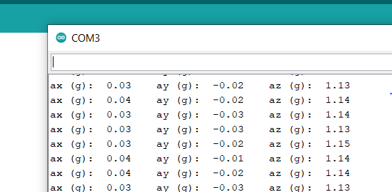
The MPU chip is laying flat in the above example. That's why the x and y g-forces are roughly zero while the z g-force is equal to 1. In other words, the g-force in the z direction is equal to g, which is 9.8 N, which physically makes sense. The following diagram details the coordinates for the chip.
We can convert the accelerometer readings into angles, which we'll need later. The following diagram and formulas from digikey are used for the conversion.
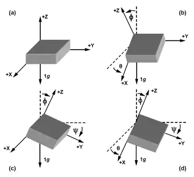
is the angle about the x axis, is the angle about the y-axis, is the angle about the z-axis. The above formulas will be implemented in the processData function.
#include <Arduino.h> // This enables us to use the arduino library in the cpp file
#include "mpu.h"
#include <Wire.h> // for I2C communication

void mpu::init(){
    // initialize mpu parameters
    Wire.beginTransmission(0b1101000); // Start communicating with I2C address of MPU
    Wire.write(0b1101011); // Access the 0x6B power management register
    Wire.write(0b00000000); // Set all parameters in register to 0
    Wire.endTransmission();
    Wire.beginTransmission(0b1101000);
    Wire.write(0b11100); // Access the 0x1C accelerometer register
    Wire.write(0b00000000); // set all bits to 0, bit 4 and 3 are set to 0 for 2g acceleration
    Wire.endTransmission();
};

void mpu::retrieveData(){
    Wire.beginTransmission(0b1101000);
    Wire.write(0b111011); // This is the starting register for accelerometer measurements (0x3B)
    Wire.endTransmission();
    Wire.requestFrom(0b1101000, 6); // read the 6 registers
    ax_raw = (Wire.read() << 8 | Wire.read()); // bit shifting, first two bytes are stored in ax (x-component acceleration)
    ay_raw = (Wire.read() << 8 | Wire.read()); // third and fourth bytes are stored in ay (y-component acceleration)
    az_raw = (Wire.read() << 8 | Wire.read()); // fifth and sixth bytes are stored in az (z-component acceleration)
};

void mpu::processData(){
    ax_g = ax_raw / 16384; // convert from raw to g
    ay_g = ay_raw / 16384;
    az_g = az_raw / 16384;
    angleX = atan(ax_g, sqrt(pow(ay_g, 2)+pow(az_g,2)))*180/PI; // acceleration in g is converted to angles in degrees
    angleY = atan(ay_g, sqrt(pow(ax_g, 2)+pow(az_g,2)))*180/PI;
    angleZ = atan(az_g, sqrt(pow(ay_g, 2)+pow(ax_g,2)))*180/PI;
}
Make sure to add the new angle variables in the header file as well:
class mpu {
    public:
        void init();
        void retrieveData();
        void processData();

    public:
        double ax_raw, ay_raw, az_raw; // store raw accelerometer data
        double ax_g, ay_g, az_g; // stores g-forces
        double angleX, angleY, angleZ; // stores angle
};
In the mpu.ino file, change the code to the following:
#include "mpu.h"

mpu mpu; // instantiate mpu class

void setup() {
    mpu.init();
    Serial.begin(9600); // set baud rate for our serial monitor
}

void loop() {
    mpu.retrieveData();
    mpu.processData();
    Serial.print("ax (angle):  ");
    Serial.print(mpu.angleX);
    Serial.print("ay (angle):  ");
    Serial.print(mpu.angleY);
    Serial.print("az (angle):  ");
    Serial.println(mpu.angleZ);
}
Upload the code and open the serial monitor to see the following:
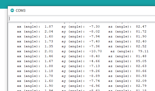
Make sure to rotate the MPU6050 to see how the angles change. To improve the angle readings, you can also retrieve the data from the gyroscope and use a Kalman filter to fuse it with the data from the accelerometer. However, we'll stick with the above code.
That's all for part 1 of this series. In part 2, we will go over motor control and implementing a PID control algorithm.